Help · Checking and documents
Cutting maps
Cutting maps show how every part is cut from sheets and bars of stock. The studio lays them out by itself after each change, so the maps always match the model.
Open the cutting maps
Click Documents in the header. The window has three parts:
- A strip under the title: the Machine list, your current settings in one line, and the Settings button.
- On the left, every sheet material and profile of the project with its result, for example 2 sheets · 78%. Below them is the Drawings section (see Drawings).
- On the right, the maps of the selected material and a table of its parts.
Each kind of part gets a number. Identical parts — same material, size, edge band, holes and other work — share one number and are counted together. The same numbers are used in the parts list, on the drawings, on part labels and before the part's name in the Elements list. Renaming a part doesn't change its number.
Shapes (free-form parts) are not cut from sheets, so they have no map. Their sizes are in the parts list and on their drawings.
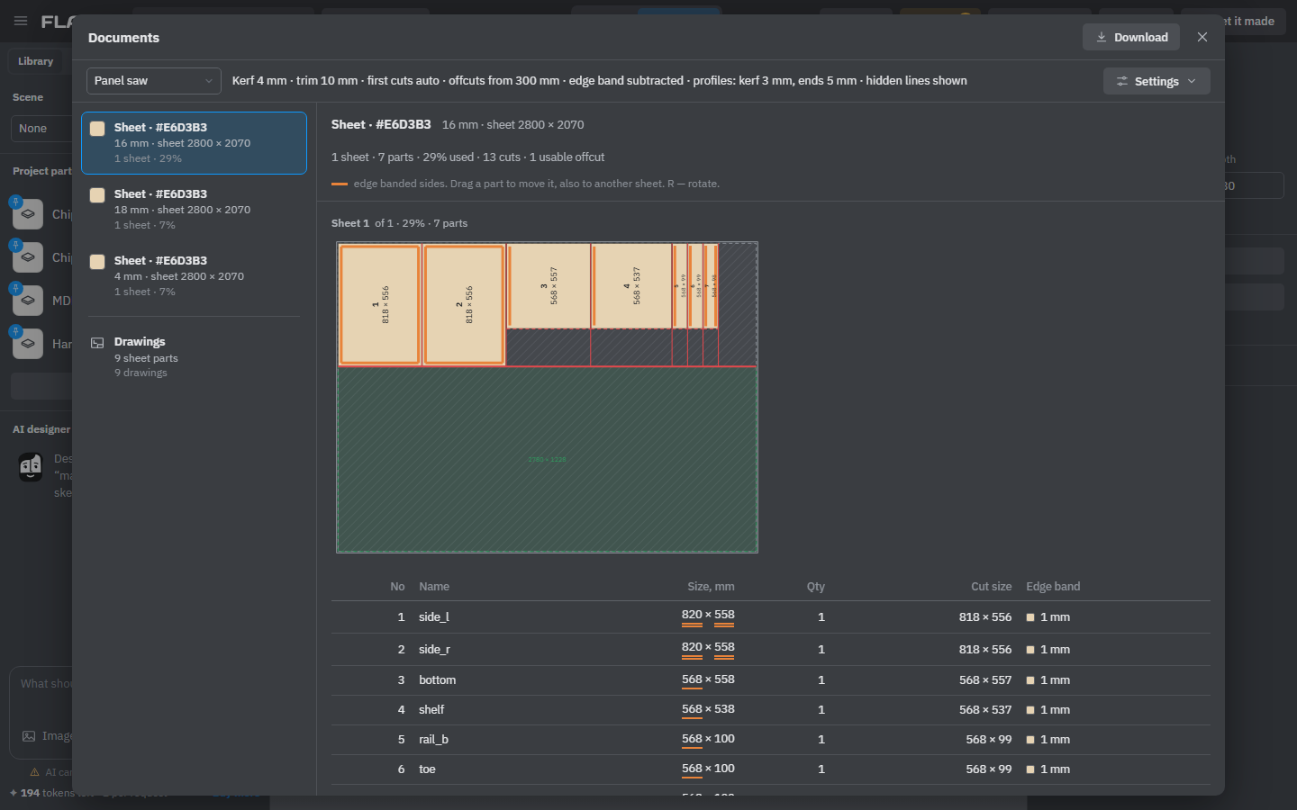
Read a sheet map
- Each part shows its number and its length × width. A part turned on the sheet has its label along its length.
- On a panel saw layout the cuts are red; the first cuts, which run right across the sheet, are thicker.
- Waste is hatched. Leftovers big enough to use later are green.
- On a material with grain, thin stripes run along the sheet length.
Above the maps, a line sums up the material: sheets, parts, how much of the stock the parts use, the number of cuts and usable offcuts. Each sheet has its own line, such as Sheet 1 of 2 · 84% · 9 parts. Since stock is usually bought by the whole sheet, try to fit the parts on fewer sheets.
The table under the maps lists the parts of this material: number, name, size, quantity, the cut size when it differs, the edge band and the grain. Lines under a size show edge banding on one or both sides of that length. If a part is bigger than the sheet or bar, a note above the maps says which one doesn't fit: make the stock bigger in the material, or the part smaller.
Choose the machine
The Machine list at the top of the window sets how sheets are cut:
- Panel saw — every cut runs right through the piece, as on a sliding table saw. The map is drawn with saw cuts.
- CNC router — the cutter goes around each part. Shaped parts are laid out by their outline, and small parts can sit inside the cut-outs of big ones.
Settings
Click Settings to open the settings under the strip. They are saved with the project. The browser also remembers the last ones you used, for your next new project.
Sheets
- Kerf (panel saw) — the width of the saw blade, the gap between parts. 4 mm by default.
- Trim (panel saw) — how much is cut off every edge of the sheet before the parts are cut. Factory edges are rarely clean and square.
- First cuts (panel saw) — Along cuts strips along the sheet length first, Across cuts strips across the sheet, Auto picks whichever uses less material.
- Tool Ø (CNC router) — the cutter diameter, which is the gap between parts.
- Margin (CNC router) — the distance from the sheet edge to the parts.
- Usable offcut from — leftovers this big or bigger are marked as usable. 0 turns the marking off.
- Subtract edge banding — parts are cut smaller by the thickness of their edge band, so the finished size is right. The table then shows a Cut size column.
Profiles
- Kerf — the saw blade width between pieces.
- End trim — how much is cut off each end of a bar.
The Drawings group has the Hidden lines option (see Drawings).
Grain direction
Wood grain, veneer and other patterned decors have a direction. When you choose such a decor for a sheet material, its material window ticks Grain runs along the sheet length; a plain colour leaves it off. You can change the tick in the material window (see Materials and decors).
On a material with grain, each part lies on the map with the pattern running the way you see it in 3D — by default along the part's length — and the map never turns it. The Grain column of the parts table says Along (with the part's length), Across (with its width) or Any (it may be turned). A part with grain doesn't fit when its length is longer than the sheet length, even if it would fit across.
Move parts by hand
In your studio you can rearrange a sheet map yourself:
- Drag a part to another place on its sheet, to another sheet, or to Drop here — new sheet that appears at the end while you drag. The part snaps to the edges and to its neighbours, keeping the kerf between them. A place where it would overlap another part is refused.
- Click a part to see its number, name, size and place on the sheet. Press Rotate or R to turn it. Only parts that may be turned (no grain, or grain Any) can be rotated.
- Every manual change is a step in the history: Ctrl+Z undoes it.
- Re-optimize discards your changes and lays the material out again. The material is marked edited in the list while it has a manual layout.
If the parts of that material change later, the studio lays it out again by itself and tells you so above the maps.
On a CNC router layout with shaped parts the parts are nested by outline automatically and can't be dragged. On a panel saw, a hand-made layout that can't be cut with through cuts gets a warning. In a project opened by a view link the maps can only be looked at.
Profiles and bars
Profiles, tubes and timber are laid out along bars of the stock length. Each bar shows its pieces, what is left, and how much of the length is used. Bars with the same set of pieces are shown together.
See also: Drawings, Downloads, Materials and decors, Edge banding.