Help · Parts and assembly
Connectors
A connector is a port on a part. Parts with matching connectors snap together when you drag one to the other: a pipe into a fitting, a leg under a cabinet, a handle onto a door. A connector can also drill the holes for a joint. Connectors are an Advanced feature: turn on ☰ → Advanced tools.
Add a connector
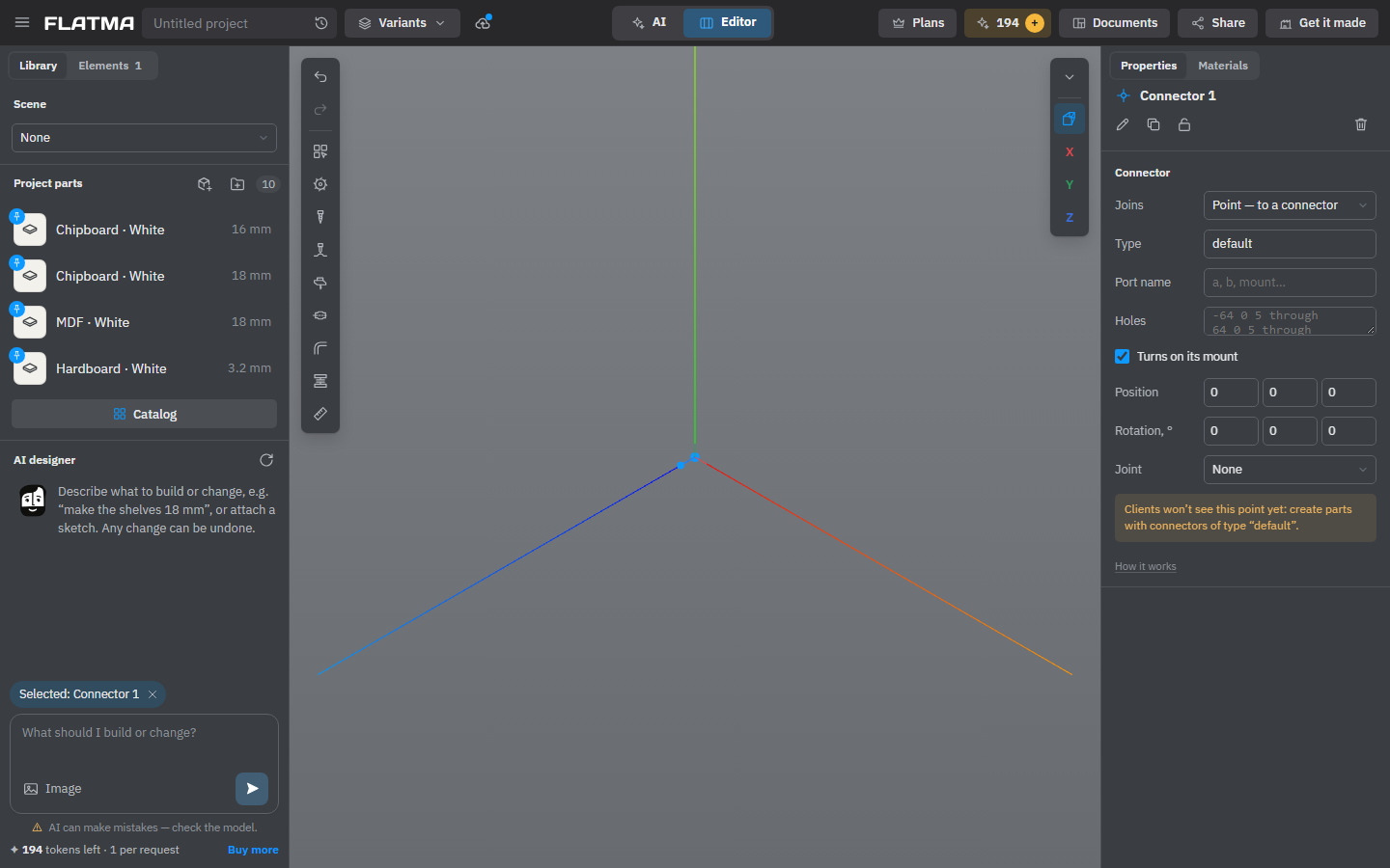
Open Catalog → Free shapes and click Connector. Drag it into place: on its own it snaps to corners, face centres and other connectors. Its short tail shows which way its Z axis points, and the selected connector also shows its X, Y and Z axes.
A connector is most useful inside a part. Make the part with New part or open it with Edit part, add the connectors there and save: every time you place the part, its connectors come along. See Project parts and My parts.
So that they don't clutter the view, connectors show only when you need them: on the selected object, while you drag an object (its own and the ones it can join), and all of them while you edit a part. Connectors you placed by hand also show in the Editor with Advanced tools on. Shared views never show them.
Point or plane
Select the connector. The Connector block in Properties starts with Joins:
- Point — to a connector. It joins another point connector of the same Type, matching its axes. For parts that plug into each other, give the type a name with an ending: a socket
name:ftakes a spigotname:mof the same name, axis to axis. Z points out of the part. For example, a pipe end isdn50:mand the fitting's socket isdn50:f. - Plane — onto any face of a part. The part sits on any face of another part with this connector's Z going into that face, and slides along it. This is how handles, legs and drawer slides stand on a part. Once it stands on a face, it follows that part: it moves and stretches with it, opens with a door and hides with it.
A plane connector has a Holes field: one hole per line, x y Ø depth or x y Ø through, in mm along the connector's own axes. They are drilled into the part it sits on. For a handle with 128 mm between its screws, the two lines are:
-64 0 5 through64 0 5 through
Port name (a, b, mount…) names the port, so the AI can say which ends to join.
Joint holes
A connector can drill the holes for a dowel, a confirmat or a shelf pin where two parts join at it. Choose the Joint: None, Dowel 8×30, Dowel 6×30, Confirmat 7×50, Shelf pin 5 or Custom. Then:
- This part: Ø, depth — the hole in the part the connector belongs to.
- Other part: Ø, depth — the hole in the part joined to it. 0 means no hole.
- Swap parts — exchanges the two holes when they came out the wrong way round.
- Count, step — a row of identical fasteners along the connector's X axis, centred on it.
The holes are drilled across the joint into both parts. They follow the parts when you move them and disappear when the parts come apart. Fasteners chosen from the list are counted in the specification; a Custom one isn't, because the studio doesn't know what it is.
Turns on its mount
Turns on its mount is on by default: the part can turn around this connector and stays attached. On a face it turns flat on the face, around the connector's axis; at a point joint it turns around the joint's axis. A part standing on a face shows only the rotation arrow for that axis. Switch it off to keep the part from turning at all, for a handle that must stay level, for example.
Position and Rotation, ° place the connector in the axes of the part or group it is in.
While you edit a part, its connectors don't join anything: the scene is the part itself. Joins are made when the parts meet in the project.
See also: Project parts and My parts, Fasteners and hardware, Library and catalog.