Help · Checking and documents
Drawings
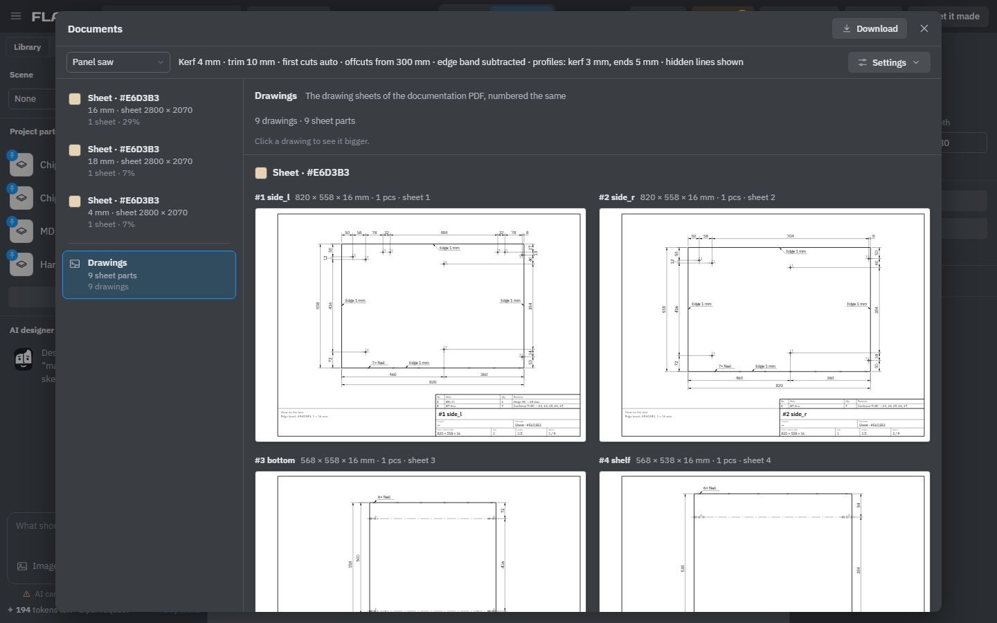
The studio draws every part that needs a drawing: holes, grooves, cut-outs, angled cuts and sizes, on an A4 landscape sheet. The drawings are always up to date with the model.
Where to find the drawings
Click Documents in the header, then Drawings at the bottom of the list on the left. On the right are all the drawings of the project, in the same order and with the same sheet numbers as in the documentation PDF (see Downloads). Each card shows the part's number, name and size, how many there are and its sheet number. The cards fill in one by one: a big part takes a moment to draw.
Not every part needs a drawing. A plain rectangular panel and a profile with square cuts are fully described by the parts list, so the Drawings section lists them under a note instead. A drawing is made for:
- sheet parts with holes, grooves, pockets, shaped outlines or cut-outs, or with nails;
- profiles and bars with holes or angled cuts;
- every shape (free-form part).
In the parts list of the PDF, a part with a drawing says which sheet it is on, for example drawing 2.
Sheet parts
A panel is drawn as one view on its face, long side horizontal, with all the work on it. The face with more machining is the one you see.
- Holes are numbered on the view. A table above the title block explains each number: the hole, such as Ø8 thru (right through) or Ø8×12 (12 mm deep), how many there are on the sheet, and the fastener that goes in it with the parts it joins. Holes in the edges read like Ø8×30 edge.
- Pockets, grooves and rebates show their depth, such as depth 5.
- Rounded corners of the outline and cut-outs show their radius, such as R60.
- Dimensions run in chains from the nearest edges; the overall size is at the bottom and on the left. Equal steps are written as one, such as 4×32=128.
- Edge banding is called out along each banded side, such as PVC edge 2 mm.
- Notes under the view list the sides, the edge band and the direction of the grain.
A sheet bent on lines is drawn as its flat pattern with the bend lines (up or down), a table of bends and a small view of the bent part.
Side A and side B
When a panel has blind work on both faces — holes, pockets or grooves that don't go right through — it gets two sheets. Side A is the face with more machining. Side B is the same part turned over around its length, with its own work and dimensions measured as you see them after turning the panel. Both sheets share one number, such as 5A and 5B. Holes that go right through show on both.
Profiles and bars
A profile is drawn along its length, with a view from above when it has holes or cuts of its own there, and an end view showing the section. Holes read like Ø8 thru, Ø8 one wall or Ø8×12; angled cuts show their angle, such as 45°. A long bar with nothing in the middle is drawn with breaks, but its dimensions are real.
A bent tube or bar gets a drawing for the bender: the straight blank with marks where each bend starts and ends, a Bending (YBC) table — the straight before each bend (Y), the turn of the tube (B), the bend angle (C) and the radius (CLR) — and a view of the bent part.
Shapes
A shape is drawn in three views — front, top and left — plus an isometric view, with dimensions to its steps, grooves and hole centres, and diameters such as 4× Ø8. Visible edges are solid, hidden ones dashed, axes of holes and turned parts dash-dotted.
Look at a drawing up close
Click a drawing card to open it full screen. The sheet stays sharp at any zoom, up to 64 times.
| To | Mouse or touch | Keys |
|---|---|---|
| Zoom in or out | Wheel or pinch, the − and + buttons; double-click zooms in, Shift+double-click zooms out | + / − |
| Move the sheet | Drag; one finger on a touch screen | |
| See the whole sheet | Click the percentage between − and + | 0 |
| Next or previous sheet | The arrows on both sides of the page count | → / ←, PageDown / PageUp |
| Close | The × button | Esc |
After the last sheet of one drawing comes the first sheet of the next. While the viewer is open, keys don't reach the studio: Esc only closes the viewer and Delete doesn't delete anything.
Hidden lines
In Documents → Settings, the Drawings group has Hidden lines: dashed lines for edges hidden behind the shape. It is on by default. Turn it off for cleaner views of complex shapes. On a panel, work on the back face stays dashed either way, unless the panel has its own side B sheet.
The drawings are made from the model automatically. Check every size before you order or start cutting. When too many dimensions crowd one place, the drawing says how many were left out; take them from the DXF files.
See also: Cutting maps, Downloads, Fasteners and hardware, Before you make it.